Summary: Steve Jobs's NeXT computer company made a keyboard in 1988. With no prior electronics experience, I tried to get it to work over USB. To do so, I had to go way deeper than I ever expected - all the way back over 100 years to broadcast radio standards from the 1920s. I learned tons and tons, and had a lot of fun.

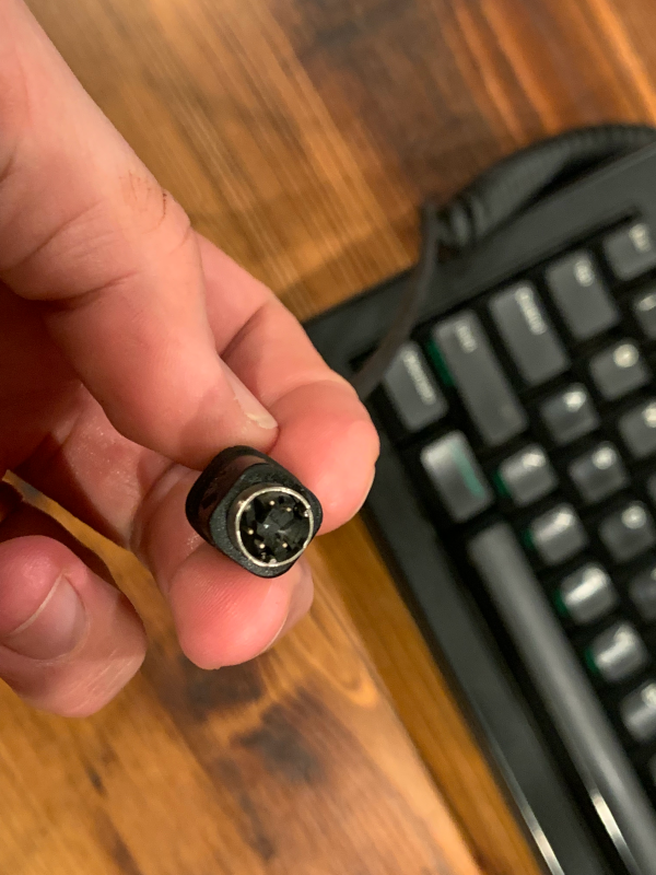
I came across a NeXT keyboard and mouse in pretty terrific condition recently. It's a beautiful device, and the keys feel really great, but the keyboard predates USB by a lot so it wasn't immediately clear how I could connect it to any modern computer. It has this weird 5-pin round connector, which I eventually learned is a "DIN" connector, of the "non-ADB" flavor.

The connector even has a little embossed NeXT logo - it's pretty fancy:

It matches the famous and beautiful NeXT logo at the top of the keyboard:

Happily, other people have worked to get these old NeXT non-ADB keyboards to work over USB. There's a quite thorough tutorial on adafruit, complete with code. I have never really done any software work at this level - I've spent my software career working on big services and distributed systems - but this seemed like an approachable project, so I bought an Arduino Micro board and a 5-pin DIN connector off of Digikey.
I eagerly installed the tutorial's software and... nothing really worked quite right. Keys sometimes worked, but sometimes didn't. The "A" key worked great, but if I pressed "X" or "C" then I would never get any signals again until I unplugged it and replugged it. Something was wrong.
My first thought was that I must have wired something wrong, but after
triple-checking I started to doubt the software. After some effort, I figured
out how to print output to my host machine over USB 1. I battered around for
a bit, and then discovered that my keyboard seemed to be sending a different
"idle" signal. I was getting 0x200C00, not 0x200600. And all the modifier
keys seemed to be off by one bit from the expected values in the sample code.
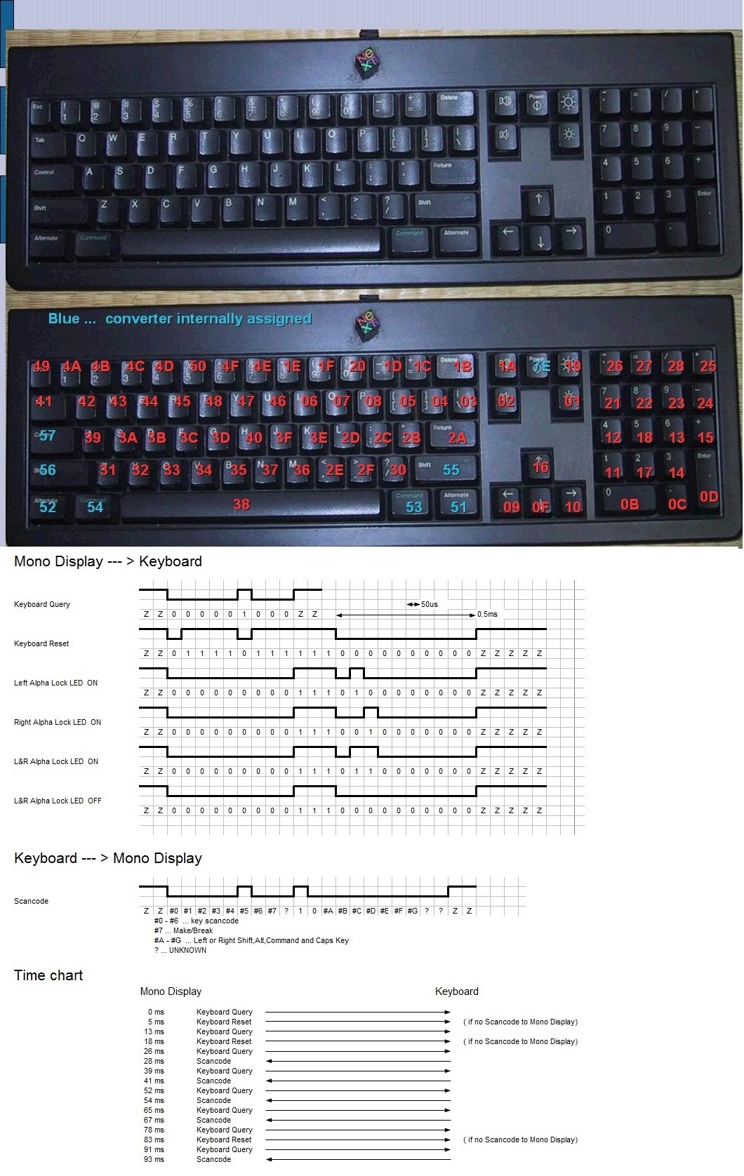
I started changing some of the keycodes to match what I observed, thinking that some of the values might be different for different models of the keyboard. But then I noticed that the keys were not stably giving the same codes! Something must be more deeply wrong. I started to wonder about this diagram in the original Adafruit tutorial. Was this really the timing of things?

I found an article from someone named Drak who seemed to have similar doubts about the timing, and who noted that the time interval might be as high as 54 microseconds.
And then I found that the open source TMK keyboard firmware has an implementation for non-ADB NeXT keyboards, with an intriguing comment attached:
/* The keyboard sends signal with 50us pulse width on OUT line
 * while it seems to miss the 50us pulse on In line.
 * next_kbd_set_leds() often fails to sync LED status with 50us
 * but it works well with 51us(+1us) on TMK converter(ATMega32u2) at least.
 * TODO: test on Teensy and Pro Micro configuration
 */
Apparently I wasn't the only one who was suspicious of the 50 microsecond claim.
Even with different timing values, things were still strange about this protocol. I mean, why would the engineers at NeXT send 22 bit messages? And why were they sometimes 23 bits? Those are bizarre design decisions. I hypothesized that maybe they were sending two 10-bit messages (composed of 1 start bit, 8 bits of data, and 1 stop bit), with a little blip in between of arbitrary-but-usually-smallish length). This would make a lot more sense: it would use typical 8-bit data packets, and the variably-sized chunk in the middle would allow the receiver to set up a trigger for a falling edge to resynchronize when reading the second byte.
But also, why 51 microseconds? That seemed like a bizarre pulse width. I looked
at a table on
Wikipedia of
common clock frequencies used in electronics, but found nothing that looked too
close to 20 kHz - until once, when configuring the serial monitor to get debug
data out of my Arduino, I noticed the 19200 baud option. Eureka! 19200 baud
means sending bits out at 19.2 kHz - in other words, with a pulse width of
52.08 microseconds! Could the NeXT non-ADB keyboards be using a 19200 baud
signal?
Another possibility lingered in my mind. This was a 33 year old keyboard. Maybe the electronic components in it had just worn out, drifting over time to work at a slightly slow speed. Maybe they had originally been designed for 20kHz, and maybe that Japanese guy's diagrams had once been correct, but time had eaten away. I found a tantalizing clue in this direction from a mention on a mailing list from 2003 where someone mentioned that their old NeXT keyboards seemed to be going bad. Maybe they went bad because the clock slowly broke, rendering the keyboard slowly more demented.
Maybe?
Signal analysis with Arduino is not trivial
These questions were really bugging me so I started trying to add
instrumentation to the Arduino code to keep track of when bits started and
ended. This turned out to be futile; I didn't realize at the time, but the
Arduino libraries are relatively high-level, and so functions like
digitalWrite and digitalRead can compile into dozens of instructions,
including pointer dereferences, and can take many clock cycles.
The Arduino Micro's ATMega32u4 microcontroller has a 16MHz clock, so each clock cycle takes 62.5 nanoseconds. It doesn't take that many clock cycles for an Arduino function call to take several microseconds, then - which mean that my naive, readable code was not very good at measuring behavior of this signal, since I suspected that the difference between 50 and 51 or 54 microseconds was problematic. I kept getting data that made no sense, which were really more about my inability to sample the signal efficiently.
So anyway I bought an oscilloscope
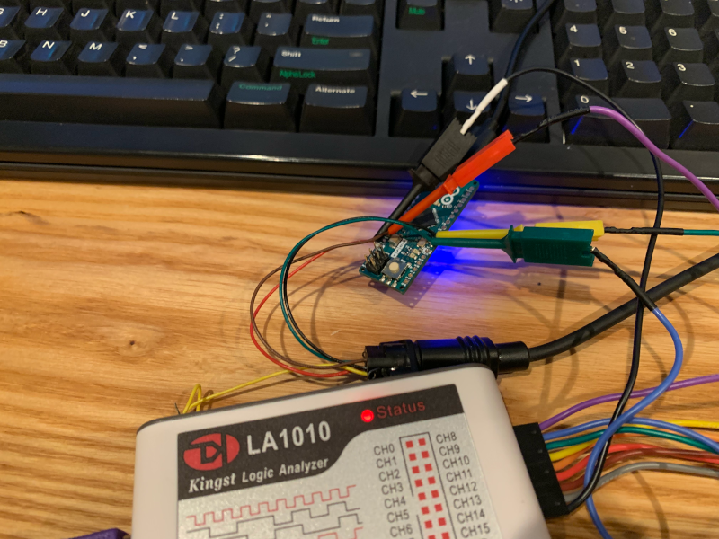
So I decided it was time to get an oscilloscope and a logic analyzer. That's when I realized that I had, somehow, become obsessed with figuring out the frequency of this obscure keyboard with a proprietary, dead protocol. I literally was lying awake at night just wondering: what were the designers thinking?
My oscilloscope came in the mail, and I watched a quick tutorial video on YouTube and plugged it in with a bit of advice from friends, and quickly isolated the signal - and there it was, 52 microseconds!

This was a wonderful moment. I could finally see the signal right there in front of me, flickering on the screen. But I found the oscilloscope a little hard to use when trying to get a precise measurement of the pulse width. I have no doubt that anyone with more experience than me could do better... but I had another gadget to try.
Logic analyzers
So, logic analyzers are pretty amazing:

This gadget takes samples of the voltage of a pin at a rate of 100 MHz, measuring the value of each wire every 10 nanoseconds. It was dirt cheap on Amazon, and incredibly it even comes with a nice-enough GUI that works immediately on Linux - no nonsense with Wine or anything. This tool is easily good enough to get a crispy, clear view of what was happening:

A few things popped out:
- The signal looks like it really is two 9-bit messages, separated by a 1-pulse-width boundary.
- The pulses were extremely consistently 52.74 +/- 0.02 microseconds wide. If the electronics were aging out, they had at least aged very, very consistently.
Here's another image showing those timings - note the numbers on the right, which measure the gaps between green lines:

My first reaction to this was wow, this cheap logic analyzer is like magic. My second reaction, though, was even more confusion. 52.74 microseconds corresponds to... 18.960 kHz? What the heck is that?
I now had the tools to write a better bit of software for the USB converter. I knew the pulse width, and I could consistently get exactly the right bit patterns for any keypress or combination.
But... I couldn't let the frequency question go. Why 18,960 hertz for the signal? I decided it was time to crack open the keyboard and look at the components.
Into the belly of the beast
I took off the screws on the back of the keyboard. I was confused at first until I realized two of the screws are hidden cleverly under the chunky rubber feet of the keyboard.


Then I got a good look at the PCB. The first thing I noticed was the massive integrated circuit at the top with a Motorola logo on it. I tried Googling it but couldn't find much of anything.

I flipped the PCB over... and noticed it had some markings. They looked like
labels, indicating the use of parts on the other side. One looked especially
curious: CERALOCK. I looked up the name, and "Ceralock" appears to be a
manufacturer of oscillators and resonators - the low-level components that can
be used to set the frequency of electronic signals. Maybe this is where the
component lies!
And indeed, directly across form the Ceralock marking was this little orange tower:

That's a CSB455E. A 455 kHz resonator. So - something here is being driven at 455 kHz. Could it be the bits from the keyboard? I played with the number a bit... and discovered then:
455 kHz / 24 = 18,958 hertz.
I think my jaw literally dropped. That's almost exactly what I had observed using the logic analyzer. This was incredibly satisfying! I finally had the answer to a long mystery!
The NeXT non-ADB keyboards have a pulse width of 52.74 microseconds, because they send data every 24 ticks of a 455 kHz clock.
455?
One thing remained: why 455 kHz? It's such a strange number for a computer: not a simple power of 2, which makes it harder to do the math when scaling the frequency.
I asked some of the wise old electronics hands I work with at Rubin. Adam Thornton and Fritz Mueller had the answer right away: you see 455 kHz clocks all the time in electronics, especially older stuff, because they are extremely commonly used in AM radio receivers.
There were gazillions of these little 455 kHz components manufactured over the years to supply the radio industry, which makes them dirt cheap. They produce a frequency that is close enough to 19,200 baud to get by, which is nice too. So the NeXT engineers probably used one because it was a simple, cheap component that could do the job.
Okay... but why are they used in AM radios? Well, this turns out to be an age-old question, and one which goes back a long way. I don't really understand all of the details, but from what I can gather, AM radios require a little clock component, and it's desirable for this component to not be too close to any actively-used broadcast frequencies.
In the Americas, AM radio can be broadcast only on specially designated frequencies - multiples of 10 kHz: 440 kHz, 450 kHz, 460 kHz, and so on.
But in the rest of the world, AM radio is broadcast on multiples of 9 kHz: 441 kHz, 450 kHz, 459 kHz, 468 kHz, and so on.
455 kHz is a nice compromise point between these "channel spacings". An AM radio receiver with that internal component at 455 kHz will work well in any market!
Epilogue
I had a blast learning all this stuff. I didn't even mention my adventures learning AVR programming: once I understood the signal well, I realized I would want timer interrupts to drive my logic, and found the Arduino helper libraries more burdensome than helpful - and so I swam out into the murky waters of programming-by-datasheet.
My code is available here, although I must sternly warn you that I made no attempt at portability and I cannot vouch for the code; I did it to learn my own way. But I sure had a lot of fun, and expect I'll be back to explore more in the world of electronics.
-
Arduino libraries make the Arduino side of this easy; all you need is
Serial.println. But on the host computer side, I needed to learn to useminicom, which was, uhh, quite a bit more unusual. ↩